As I discribed in a earlier blog,the bandwith of my bandpass filter in the Bitx 20 was very small.Only 100KHz or so.I found this filter on the internet,and after I,ve build the filter I found out that this was the filter used in the Bitx20A from Hendricks QRP kits.Because I wanted to use the whole 20M band (14.000MHz-14.350MHz) I,decided to build the Original bandfilter which was designed in the Bitx20 V1 by Ashar Farhan.
![]() The bandpass filter is located in the upper left corner of the drawing.Notice that the drawing above is the Bitx20 V1.My Bitx20 which I describe on this blog is the V3 build.Ok,let`s build.What do we need.A piece of PCB,3X 20pf variable capacitor,2X 10pf, 3X 47pf caps, 2X 2,2pf caps, and 3X Amidon T37-6 core and a few inches of magnet wire for winding the inductors.The diameter of the magnet wire is not that important.I used 0,30mm.The inductance of the T37-6 needs to be 2uH.Put 25 windings on the core and measure the value with a LC-meter.The one`s I made where exactly 2uH.Remember to use the whole core when you put on the windings.After you finished the windings,I put on some glue with a hot glue gun,so the windings would not move on the core.
The bandpass filter is located in the upper left corner of the drawing.Notice that the drawing above is the Bitx20 V1.My Bitx20 which I describe on this blog is the V3 build.Ok,let`s build.What do we need.A piece of PCB,3X 20pf variable capacitor,2X 10pf, 3X 47pf caps, 2X 2,2pf caps, and 3X Amidon T37-6 core and a few inches of magnet wire for winding the inductors.The diameter of the magnet wire is not that important.I used 0,30mm.The inductance of the T37-6 needs to be 2uH.Put 25 windings on the core and measure the value with a LC-meter.The one`s I made where exactly 2uH.Remember to use the whole core when you put on the windings.After you finished the windings,I put on some glue with a hot glue gun,so the windings would not move on the core.
![]() After the toroids are finished,you must strip of the isolation of the wire and tin the wire ends.I started the build of the Bandpass filter to solder a Island on the PCB for the input and a Island for the output.These so called islands are copper double sided pcb from only a few mm`s.After you soldered the two islands on the filter pcb,always check that the Island pcb`s don`t make contact with the filter pcb.Before I put the parts on the PCB,I`ve measured them with the LC-meter.
After the toroids are finished,you must strip of the isolation of the wire and tin the wire ends.I started the build of the Bandpass filter to solder a Island on the PCB for the input and a Island for the output.These so called islands are copper double sided pcb from only a few mm`s.After you soldered the two islands on the filter pcb,always check that the Island pcb`s don`t make contact with the filter pcb.Before I put the parts on the PCB,I`ve measured them with the LC-meter.
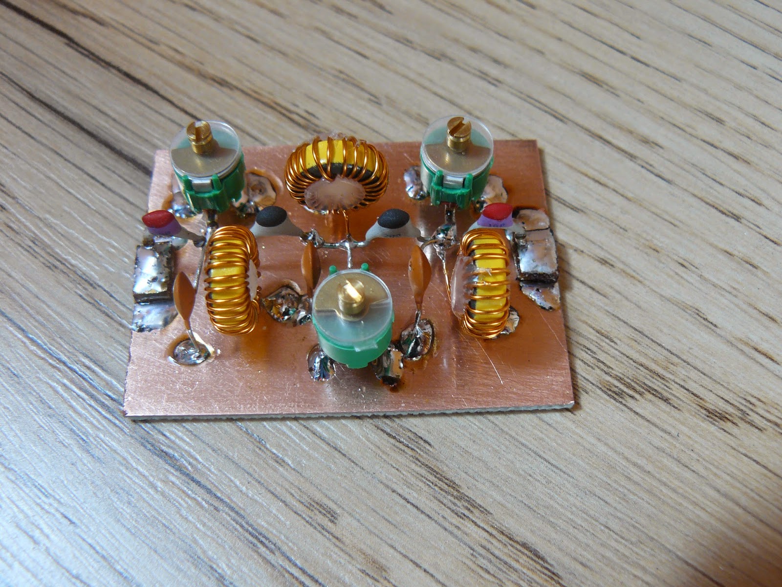
![]() If you follow the build of the Bitx20 by Ashar Farhan,you see that he used tap washer rings for the inductors.It is very important that the inductors can not "see" each other because of the magnetic field around the cores,so they won`t interfere.Therefore you need to put the cores on a 90 degree angle facing each other.When you use the Amidon cores like I did,these problems do almost not occur,but I did it anyway.On the picture bellow you see the complete Bitx20 Bandpass filter.
If you follow the build of the Bitx20 by Ashar Farhan,you see that he used tap washer rings for the inductors.It is very important that the inductors can not "see" each other because of the magnetic field around the cores,so they won`t interfere.Therefore you need to put the cores on a 90 degree angle facing each other.When you use the Amidon cores like I did,these problems do almost not occur,but I did it anyway.On the picture bellow you see the complete Bitx20 Bandpass filter.
![]() Because I don`t have a spectrum analyzer,I was not able to test it if the Bandpass filter was doing a good job on the frequency it was designed for.So I took out the earlier filter and put the new filter in my Bitx 20 V3.After I made the connections,I put the power and a antenna on the Bitx.And guess what.I didn`t hear anything,only noise.After a turn on one of the 20pf variable capacitors the stations where comming thru.I searched for a weak station and began to turn the three variable caps so that the incoming station was on his best.
Because I don`t have a spectrum analyzer,I was not able to test it if the Bandpass filter was doing a good job on the frequency it was designed for.So I took out the earlier filter and put the new filter in my Bitx 20 V3.After I made the connections,I put the power and a antenna on the Bitx.And guess what.I didn`t hear anything,only noise.After a turn on one of the 20pf variable capacitors the stations where comming thru.I searched for a weak station and began to turn the three variable caps so that the incoming station was on his best.
![]() Now it was time to adjust the filter on the transmit signal.I connected a 50 ohm dummy load and adjusted the caps for the most RF-power on the Diamond SX-200 meter.After a few whistles in the microphone the adjustment was done.Maximum power on the meter.In my case that is 1,5Watts on a 13,8Vdc.That is still no 5 or 6 Watts that is supposed to be on the Bitx20,but all of my Bitx20 builds are on that power.I will figure that out in a later stage.
Now it was time to adjust the filter on the transmit signal.I connected a 50 ohm dummy load and adjusted the caps for the most RF-power on the Diamond SX-200 meter.After a few whistles in the microphone the adjustment was done.Maximum power on the meter.In my case that is 1,5Watts on a 13,8Vdc.That is still no 5 or 6 Watts that is supposed to be on the Bitx20,but all of my Bitx20 builds are on that power.I will figure that out in a later stage.
![]() After this adjustment I heard a station in Austria calling for CQ.With only this 1-1,5 Watt on a Endfed wire antenna the HAM gave me a 5-9 and good audio rapport.On the link bellow you can see and hear the new bandpass filter.
After this adjustment I heard a station in Austria calling for CQ.With only this 1-1,5 Watt on a Endfed wire antenna the HAM gave me a 5-9 and good audio rapport.On the link bellow you can see and hear the new bandpass filter.